Worked out problems with solutions in pdf files
Allowable Load (Pallow),Factor of Safety (FS), Axial Stresses/Elongation, and Strain
- Finding internal stress in an axial member Example
A tension test is performed on a circular cylinder shaped steel specimen as shown below, compute the axial stress in the member (in MPa).
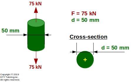 Figure 2:Tension test on a circular cylinder shaped steel specimen
- Computing strain, stress and modulus of elasticity in an axial member Example
A specimen has a length of 25 mm and a cross sectional area of 30 mm2, and is subjected to an axial load of 3000 N as shown below. If the specimen is stretched by 2 mm and is in the elastic region), compute the following:
(a) the axial stress (σ),
(b) the strain (ε) and,
(c) the modulus of elasticity (E).
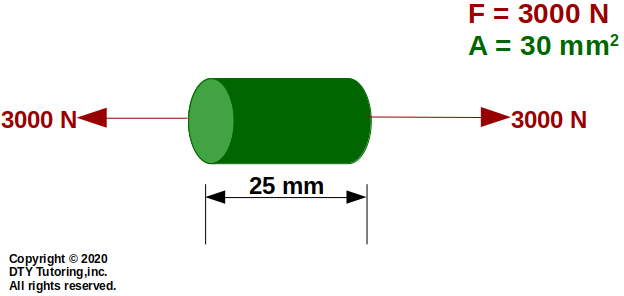 Figure 2: Axial member
- Computing average shear strain, average shear strain and relative displacement Example
![]() Figure 3:
Figure 3:
- Finding allowable average shear stress Example
Find the allowable average shear stress (Τallow) for the bolted joint lap with diameter given (db = 10 mm), if the allowable load is 2 kN (Pallow = 2 kN).
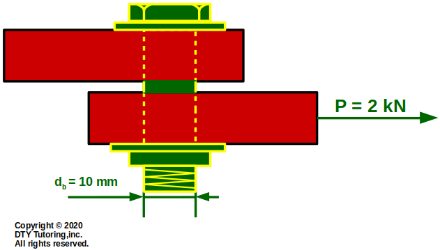 Figure 4: Shear in bolted joint
- Finding allowable load Example
Find the allowable load (Pallow) for the bolted joint lap with diameter given (db = 0.5 in), if the allowable average shear stress is 23 ksi (Τallow = 23 ksi).
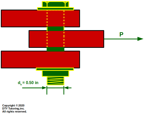 Figure 5: Shear in bolted joint
- Finding Allowable Forces/Stresses using Factor of Safety (FS) Example
![]() Figure 6:
Figure 6:
- Finding axial elongation in an axial structure Example 1
The axial structure depicted below consists of circular steel members of different areas. Compute the following:
(a) the stresses in each member, and indicate whether the stresses are tensile (T) or compressive (C),
(b) the axial displacement at B (UB), at C (UC) and at D (UD).
 Figure 7: Axial displacement
- Finding axial stress and elongation in an axial member Example
![]() Figure 8:
Figure 8:
- Finding compressive axial stress and displacement in a steel pipe column Example
![]() Figure 9:
Figure 9:
- Finding internal forces and displacement in a statically indeterminate structure (axial) Example
![]() Figure 10:
Figure 10:
Torques, Shear Stress and Relative Rotation in a Shaft
- Finding internal torques, maximum shear stress and angle of rotation in a hollow shaft Example (statically determinate)
![]() Figure 11:
Figure 11:
- Finding internal torques, maximum shear stress, and relative rotation in a shaft Example 1 (statically determinate)
A uniform steel shaft with diameter of 5 mm is depicted as shown below to transmit torques from gear A to B to C and with a modulus of rigidity (G = 20 GPa). Determine:
(a) the maximum shear stress in element 1 and,
(b) the maximum shear stress in element 2
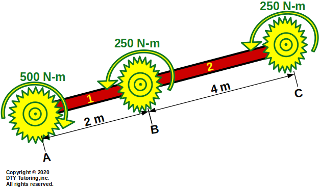 Figure 12: Steel Shaft
- Finding internal torques, maximum shear stress, and relative rotation in a shaft Example 2 (statically determinate)
![]() Figure 13:
Figure 13:
- Finding internal torques, maximum shear stress, and relative rotation in a shaft Example 1 (statically indeterminate)
![]() Figure 14:
Figure 14:
- Finding internal torques, maximum shear stress, and relative rotation in a shaft Example 2 (statically indeterminate)
![]() Figure 15:
Figure 15:
Internal Forces, Shear Force Diagram (SFD) and Bending Moment Diagram (BMD) Review
- Finding internal shear and moment at a point (in a beam)
![]() Figure 16:
Figure 16:
- Deriving shear and moment equation in a simply supported beam with triangular Uniform Distributed Load (UDL)
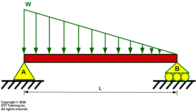 Figure 17:Simply Supported Beam with Triangular UDL
- Drawing shear and moment diagrams Review 1
Draw the shear (V) and moment (M) diagram for this overhang beam with a triangular distributed load, point load and concentrated moment.
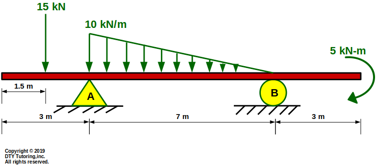 Figure 18: Overhang beam with a triangular distributed load, point load and concentrated moment.
- Drawing shear and moment diagrams Review 2
Draw the shear (V) and moment (M) diagram for this overhang beam.
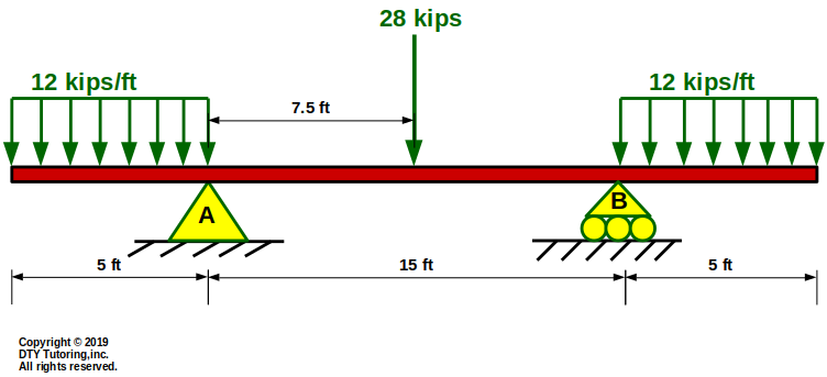 Figure 19: Overhang beam with rectangular distributed loads and a point load
- Drawing shear and moment diagrams Review 3
Draw the shear (V) and moment (M) diagram for this overhang beam.
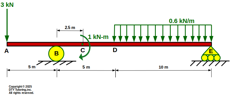 Figure 20: Overhang beam with rectangular distributed loads, concentrated moment and a point load
- Strain-displacement analysis for beams
![]() Figure 21:
Figure 21:
- Finding maximum tensile stress, radius of curvature and maximum deflection of a beam
![]() Figure 22:
Figure 22:
Normal/Flexural/Bending Stress, Shear Stress and Shear Flow Distribution in a Beam
Normal and Shear Stress Distribution in a rectangular beam
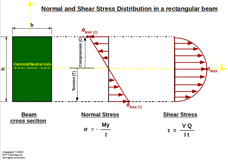 Figure 23: Normal and Shear Stress Distribution in a rectangular beam
- Finding flexural stresses in beams Example 1
A fixed wide-flange beam has a uniform distributed loading acting throughout half of the span, a point load and concentrated moment. Cross-section dimensions of the beam is given. Compute the maximum flexural tensile and compressive stresses.
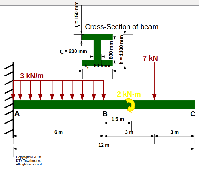 Figure 24: Fixed I-beam with UDL, concentrated load and moment
- Finding flexural stresses in beams Example 2
This simply supported beam is supported by a pin at A , a roller at B, and has a triangular distributed load acting throughout the entire span. Cross-section dimensions of the beam is given. Compute the maximum flexural tensile and compressive stresses.
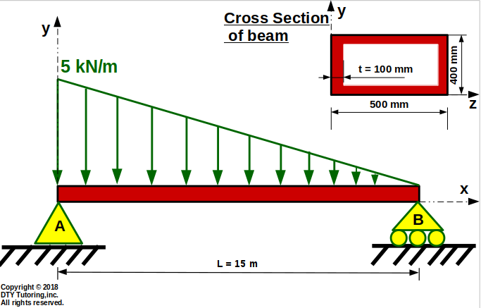 Figure 25: Simply supported beam with triangular distributed loading
- Finding flexural stresses in beams Example 3
This overhang beam is supported by a pin at A , a rocker at B, and has a uniform distributed load acting in between the supports. Cross-section dimensions of the beam is given. Compute:
(a)the flexural/bending stress at C, D, E and F;
(b)compute the flexural/bending stress and draw the stress distribution at the left support (A) ,
(c) from part (b), what are the maximum flexural tensile and compressive stresses at support A
(d) what are the maximum flexural tensile and compressive stresses that occurs throughout the entire span of the beam?
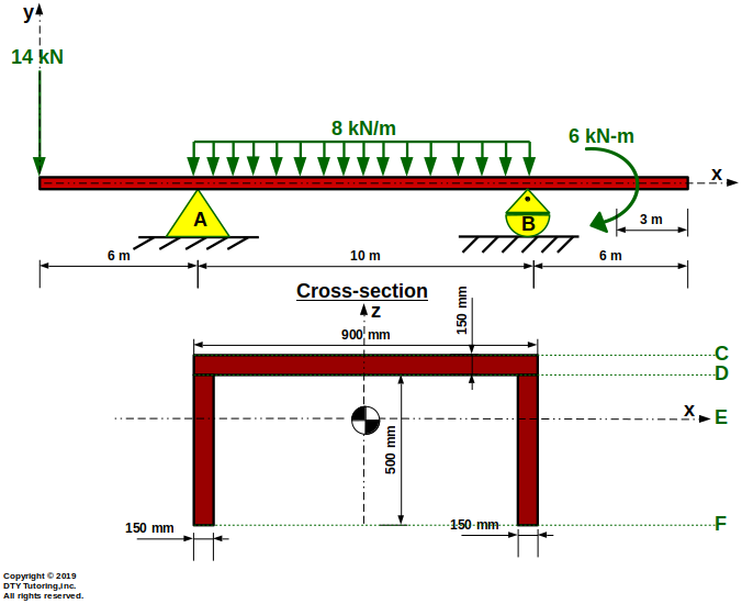 Figure 26: Overhang beam with a UDL, point load and concentrated moment
- Finding maximum compressive and tensile flexural stresses in beams
![]() Figure 27:
Figure 27:
- Design problem: choosing lightest wide flange beam given allowable stress
![]() Figure 28:
Figure 28:
- Finding maximum flexural stress and maximum shear stress in a beam
![]() Figure 29:
Figure 29:
- Finding shear stress at different locations in an inverted C channel shape
Compute the shear stress, τ, at points A, B, C, D and E for the figure shown below.Then, draw the shear stress and shear flow distribution. Also, indicate where the maximum shear stress occurs (V = 25 kN).
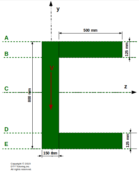 Figure 30: Inverted C-Channel Section
- Finding shear stress at different locations in a C channel shape
Compute the shear stress, τ, at points A, B, C, and D for the figure shown below.Then, draw the shear stress and shear flow distribution. Also, indicate where the maximum shear stress occurs (V = 65 kN).
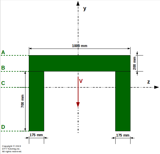 Figure 31: C-Channel Section
- Finding shear stress at different locations in an unsymmetrical I shape beam and drawing shear stress distribution
Compute the shear stress, τ, at points A, B, C, D and E for the figure shown below.Then, draw the shear stress and shear flow distribution. (V = 50 kN)
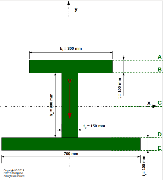 Figure 32: Unsymmetrical Wide Flange Beam
- Finding maximum shear stress in a hollow circle and drawing shear flow distribution
Compute the maximum shear stress, τMax, for the tubular steel beam as shown below. Then, draw the shear flow distribution(q).(V = 75 kN).
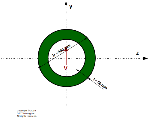 Figure 33: Tubular Steel Beam
- Finding shear stress at different locations in a hollow rectangular shape beam and drawing shear stress distribution
Compute the shear stress, τ, at points A, B, C, D and E for the figure shown below.Then, draw the shear stress and shear flow distribution. (V = 80 kN)
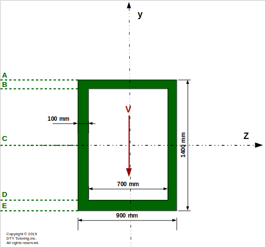 Figure 34: Hollow Rectangular Shaped Beam
- Finding shear stress at different locations in a T shape beam
Compute the shear stress, τ, at points A, B, C and D for the figure shown below. Then, draw the shear stress and shear flow distribution. Also, indicate where the maximum shear stress occurs (V = 40 kN)
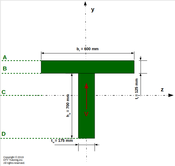 Figure 35: T beam
- Given allowable shear stress in a T shape beam, find maximum load intensity(Wo) and drawing shear flow/shear stress/flexural stress distribution
![]() Figure 36:
Figure 36:
- Finding allowable shear given allowable shear flow in a symmetrical I shape beam and drawing shear flow distribution
![]() Figure 37:
Figure 37:
- Boundary Conditions
![Boundary Conditions]() Figure 38:
Figure 38:
- Continuity Conditions
![Continuity Conditions]() Figure 39:
Figure 39:
Deflection, Slope, Curvature Equations (Double Integration Method, Euler Bernoulli Beam Equation), Deflection Shape and Superposition Method
- Drawing the deflection shape
Draw the deflection shape and indicate where the maximum deflection will occur for this simply supported beam with Uniformly Distributed Load (UDL) as shown below.
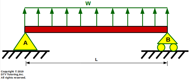 Figure 40: Simply supported beam with Uniformly Distributed Load (UDL)
- Finding slope and deflection in a cantilever beam with triangular distributed load
Determine:
(a)the equation of the slope, Θ(x), and deflection, v(x), and
(b)the maximum deflection, vMax and draw the deflected shape,
for the fixed beam with triangular distributed loading as shown below.
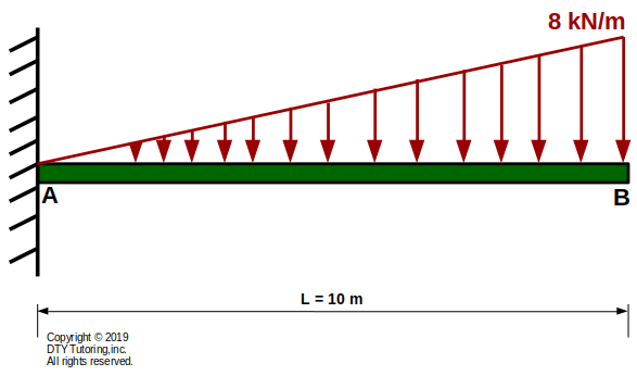 Figure 41: Fixed Beam With Triangular Distributed Loading
- Finding slope, deflection equation and maximum deflection in a simply supported beam with triangular distributed load
Determine:
(a)the equation of the slope, Θ(x), and deflection, v(x), and
(b)the maximum deflection, vMax, and draw the deflected shape,
for the simply supported beam with triangular distributed loading as shown below.
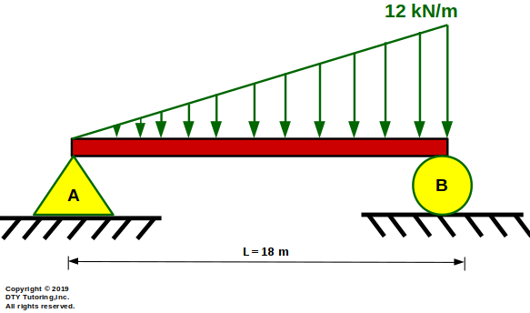 Figure 42: Simply Supported Beam With Triangular Distributed Loading
- Finding deflection equation and reactions in a propped cantilever beam with rectangular distributed load
Using superposition method, determine:
(a)the reactions,
(b)the equation of the slope, Θ(x), and deflection, v(x), and
(c) the location where the maximum deflection occurs (in meters) and the maximum deflection (in mm) if E = 200 GPa and I = 600 x 105 mm4,
(d) draw the shear, moment diagrams and the deflection shape
for the propped cantilever beam with rectangular distributed loading as shown below.
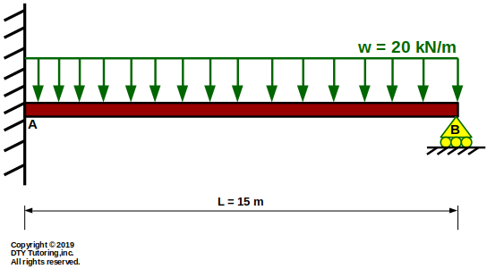 Figure 43: Propped Cantilever Beam with Rectangular Distributed Load
- Finding deflection equation and reactions in a continuous beam with rectangular distributed load
Using superposition method, determine:
(a)the reactions,
(b)the equation of the slope, Θ(x), and deflection, v(x), and
(c) the location where the maximum deflection occurs (in meters) and the maximum deflection (in mm) if E = 200 GPa and I = 450 x 105 mm4,
(d) draw the shear, moment diagrams and the deflection shape
for the continuous beam with rectangular distributed loading as shown below.
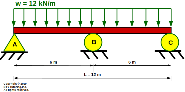 Figure 44: Continuous Beam with Rectangular Distributed Load
- Finding deflection equation and reactions in a double propped beam with triangular distributed load
Using superposition method, determine:
(a)the reactions,
(b)the equation of the slope, Θ(x), and deflection, v(x), and
(c) the location where the maximum deflection occurs (in meters) and the maximum deflection (in mm) if E = 200 GPa and I = 700 x 105 mm4,
(d) draw the shear, moment diagrams and the deflection shape
for the cantilever double propped beam with triangular distributed loading as shown below.
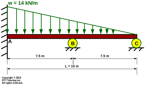 Figure 45: cantilever double propped beam with triangular distributed load
- Finding deflection equation and reactions in a fixed-fixed beam with rectangular distributed load
Using superposition method, determine:
(a)the reactions,
(b)the equation of the slope, Θ(x), and deflection, v(x), and
(c) the location where the maximum deflection occurs ,
(d) draw the shear, moment diagrams and the deflection shape
for the fixed-fixed beam with rectangular distributed loading as shown below.
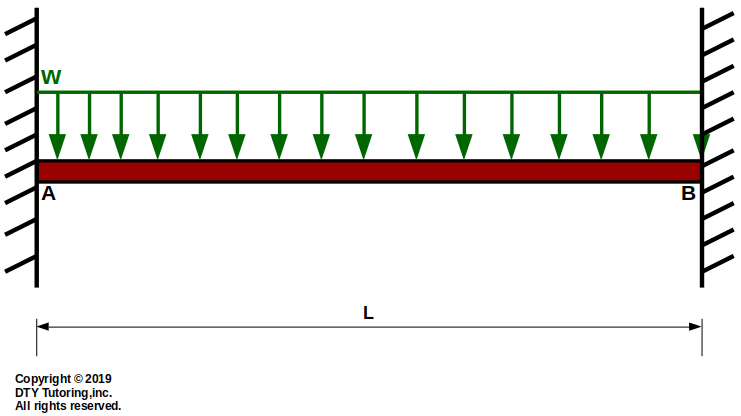 Figure 46: Fixed-fixed beam with rectangular distributed load
- Deflections and slopes of beams;Fixed-End Actions page 1
![Deflections and slopes of beams;Fixed-End Actions page 1]() Figure 47:
Figure 47:
- Deflections and slopes of beams;Fixed-End Actions page 2
![Deflections and slopes of beams;Fixed-End Actions page 2]() Figure 48:
Figure 48:
- Deflections and Slopes of Simply-Supported Uniform Beams page 1
![Deflections and Slopes of Simply-Supported Uniform Beams page 1]() Figure 49:
Figure 49:
- Deflections and Slopes of Simply-Supported Uniform Beams page 2
![Deflections and Slopes of Simply-Supported Uniform Beams page 2]() Figure 50:
Figure 50:
- Fixed-End Actions for Uniform Beams
![Fixed-End Actions for Uniform Beams]() Figure 51:
Figure 51:
- Finding slope and deflection using superposition for a fixed beam with a uniform distributed load (UDL), concentrated moment, and a point load
![]() Figure 52:
Figure 52:
- Finding deflection using superposition example 2
![]() Figure 53:
Figure 53:
- Solving statically indeterminate beam (superposition),finding slope and deflection
![]() Figure 54:
Figure 54:
Stress Block, Stress Resultants, Mohr's Circle, and Principal Stresses
Stress block sign convention
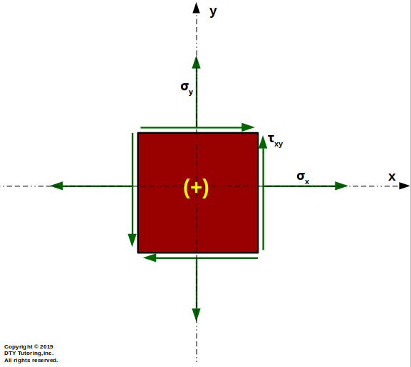 Figure 55: Stress block sign convention
- Finding stress resultants Example 1
For the given stress block below, find the principal stresses, and draw Mohr's Circle.
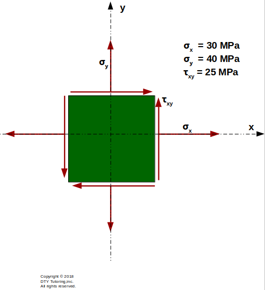 Figure 56: Drawing Mohr's Circle for a stress block example 2
- Finding stress resultants (stress block) Example 2 and drawing Mohr's Circle
For the given stress block below, find the principal stresses, and draw Mohr's Circle.
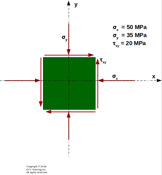 Figure 57: Drawing Mohr's Circle for a stress block example 2
- Finding stress resultants and drawing Mohr's circle Example 3
For the given stress block below, find the principal stresses, and draw Mohr's Circle.
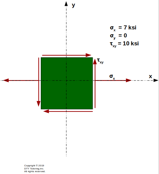 Figure 58: Drawing Mohr's Circle for a stress block example 3
- Finding stress resultants and drawing Mohr's circle Example 4
![]() Figure 59:
Figure 59:
Axial Stress and Hoop Stress in Pressure Vessels
- Pressure vessels Example 1
For the cylindrical thin-walled steel pressure vessel with inner diameter, di = 10 in, and a wall thickness, t = 0.75 in, calculate:
(a) the axial stress,σa,and,
(b) the hoop stress, σh.
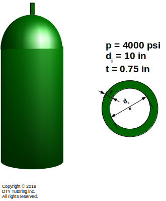 Figure 60:Cylindrical thin-walled steel pressure vessel
- Pressure vessels Example 2
![]() Figure 61:
Figure 61:
- Pressure vessels Example 3
![]() Figure 62:
Figure 62:
Column Buckling
- Buckling of Columns Example 1
![]() Figure 63:
Figure 63:
- Buckling of Columns Example 2
![]() Figure 64:
Figure 64:
- Buckling of Columns Example 3
![]() Figure 65:
Figure 65:
- Buckling of Columns Example 4
![]() Figure 66:
Figure 66: