Worked out problems with solutions in pdf files
Displacement, Reaction and Member Forces in an Axial Structure (Matrix Displacement Method,MDM)
-
Degrees of Freedom (DOF) for an axial member
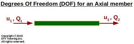 Figure 1: Degrees of Freedom (DOF) for an axial member
Finding displacement, reaction and member forces using MDM method example (Axial)
Find the displacements, member forces and reactions for this axial structure. Then, draw the axial diagram.
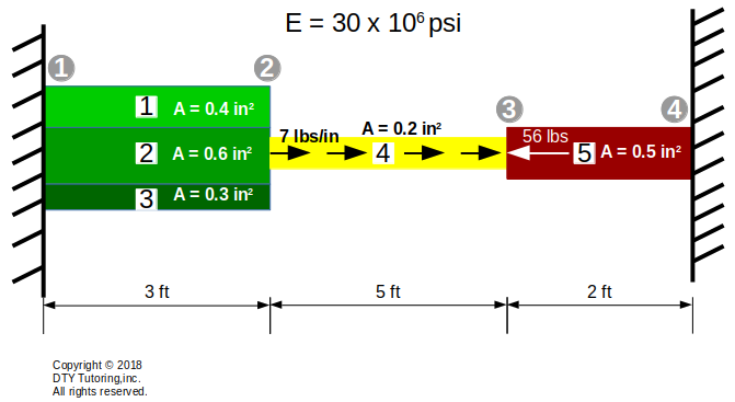 Figure 2 : MDM method example 2 (Axial)
Finding displacement, reaction and member forces using MDM method example (Axial)
Find the displacements, member forces and reactions for this axial structure. Then, draw the axial diagram.
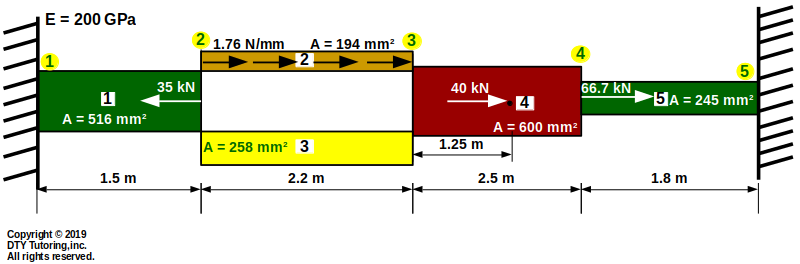 Figure 3 : MDM method example 3 (Axial)
Displacement, Reaction and Member Forces in a Truss (Matrix Displacement Method,MDM)
Degrees of Freedom (DOF) for a truss member
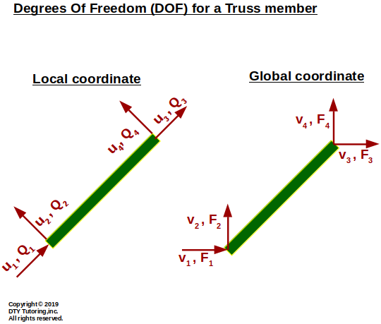 Figure 4: Degrees of Freedom (DOF) for a truss member
-
Finding displacement, reaction and member forces using MDM method example 1 (Truss)
Find the displacements, member forces and reactions for this truss.
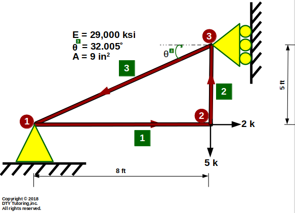 Figure 5: MDM method example 1 (Truss)
-
Finding displacement, reaction and member forces using MDM method example 2 (Truss)
Find the displacements, member forces and reactions for this truss.
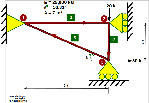 Figure 6 : MDM method example 2 (Truss)
-
Finding displacement, reaction and member forces using MDM method example 3 (Truss)
Find the displacements, member forces and reactions for this truss.
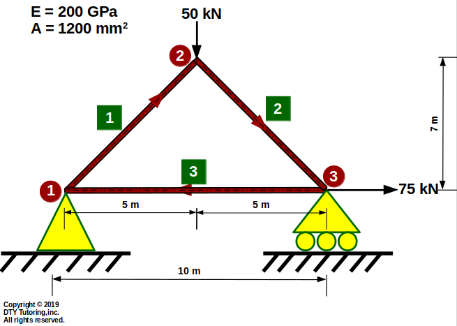 Figure 7: MDM method example 3 (Truss)
Displacement, Reaction and Member Forces in a Beam (Matrix Displacement Method,MDM)
-
Degrees of Freedom (DOF) for a beam member
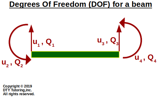 Figure 8: Degrees of Freedom (DOF) for a beam member
-
Finding displacement, reaction and member forces using MDM method example 1(Beam)
Find the displacements, member forces and reactions for this beam. Then, draw the shear and moment diagrams.
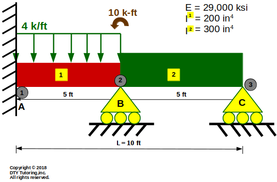 Figure 9: MDM method example 1 (Beam)
Finding displacement, reaction and member forces using MDM method example 2(Beam)
Find the displacements, member forces and reactions for this beam. Then, draw the shear and moment diagrams.
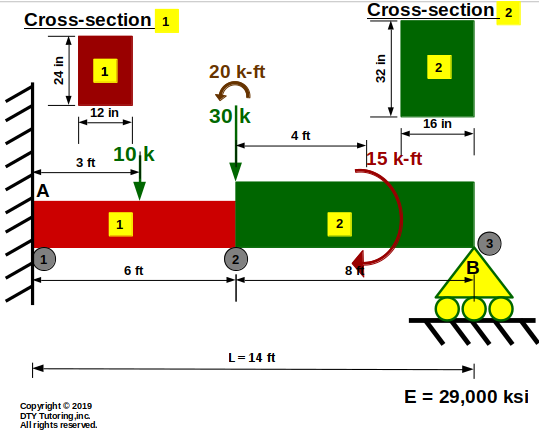 Figure 10: MDM method example 1 (Beam)
Displacement, Reaction and Member Forces in a Frame (Matrix Displacement Method,MDM)
-
Degrees of Freedom (DOF) for a frame member
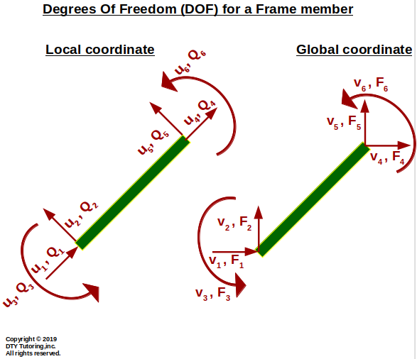 Figure 12: Degrees of Freedom (DOF) for a frame member
Finding displacement, reaction and member forces using MDM method example (Frames)
Find the displacements, member forces and reactions for this frame shown below.
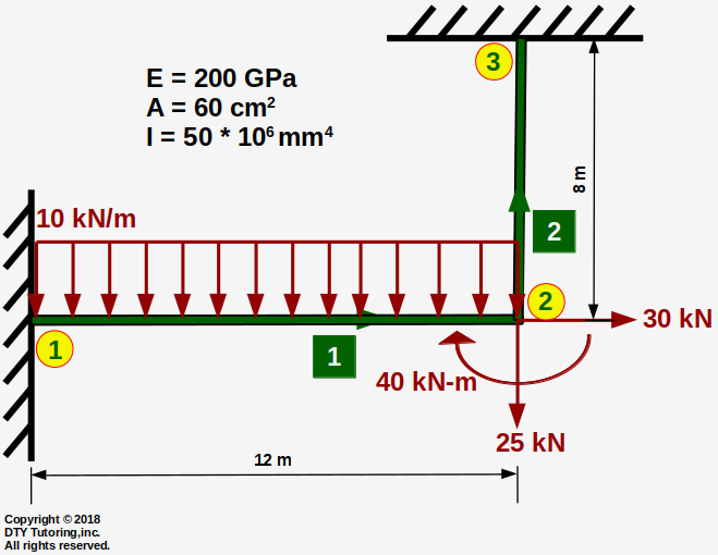 Figure 13: MDM method example 1 (Frame)
Finding displacement, reaction and member forces using MDM method example (Frames)
Find the displacements, member forces and reactions for this frame shown below.
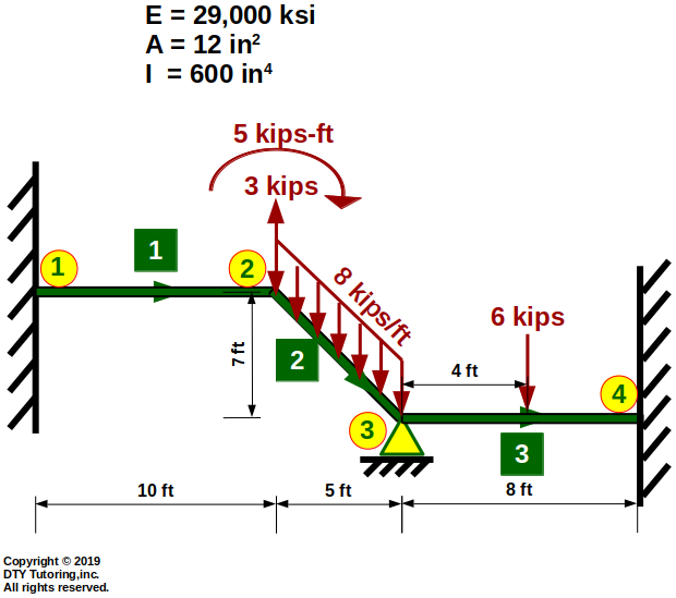 Figure 14 : MDM method example 2 (Frame)
Qualitative shear and moment diagrams
What is an inflection point (or point of contraflexure)? Where does it occur in the beam?
Inflection point (or point of contraflexure) is the point in the beam where the moment diagram changes sign (from + to - or vice versa) and is the point where the deflection curve changes the direction of curvature.
Qualitative shear and moment diagrams example 1
Draw the qualitative shear and moment diagram and the deflection shape for the cantilever double propped beam as shown below. Indicate where the inflection point(s) occur.
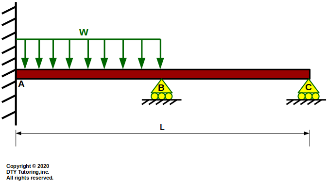 Figure 15 :Cantilever Double Propped Beam
Qualitative shear and moment diagrams example 2
Draw the qualitative shear and moment diagram and the deflection shape for the continuous beam as shown below. Indicate where the inflection point(s) occur.
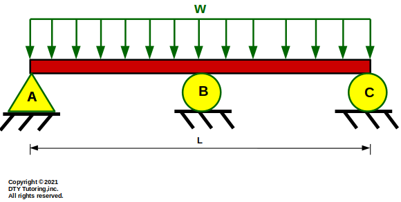 Figure 16: Continuous beam subjected to distributed loading
Qualitative shear and moment diagrams example 3
Draw the qualitative shear and moment diagram and the deflection shape for the continuous overhang beam as shown below. Indicate where the inflection point(s) occur.
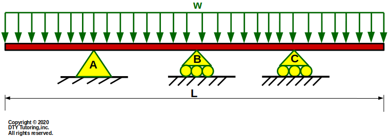 Figure 17: Continuous overhang beam
Qualitative shear and moment diagrams example 4
Draw the qualitative shear and moment diagram and the deflection shape for the fixed beam on both sides with an internal hinge and a UDL at midspan as shown below. Indicate where the inflection point(s) occur.
 Figure 18: Fixed Beam on Both Sides With Hinge and UDL at midspan
Fixed end forces derivation