Worked out problems with solutions in pdf files
Magnitude and Direction of a Resultant Force
- Finding resultant force, magnitude and direction Example 1
Find the magnitude and direction of the resultant force for the figure shown below.
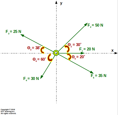 Figure 2: Finding resultant force
- Spring problem Example
For the figure shown below, F2 has a spring stiffness, k= 0.4 kN/m, with a stretched length of s = 0.5 m; F2 and F3 are regular forces. Find the magnitude of the force F3.
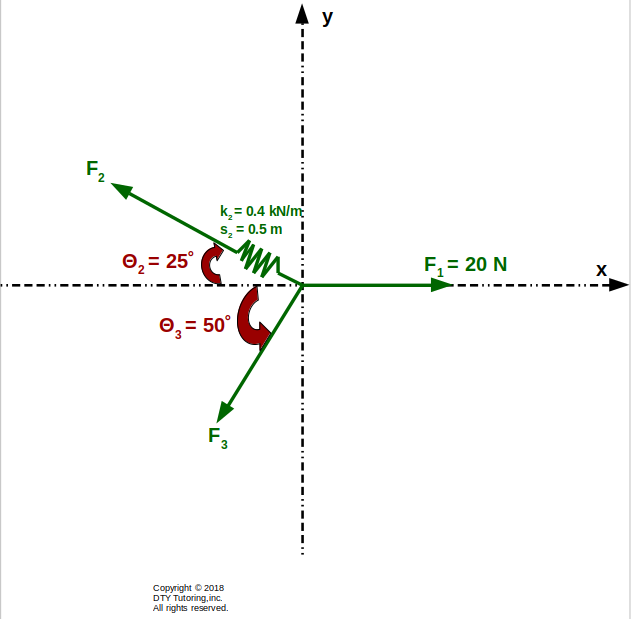 Figure 3:Resultant forces with a spring
- Moment of force Example
For the figure given below, compute the resultant moment about point A and B due to the forces acting on the structure.
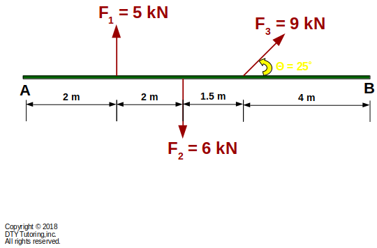 Figure 4:Finding resultant moment
- Couple Moment Example
![]() Figure 5:
Figure 5:
- Support Reactions
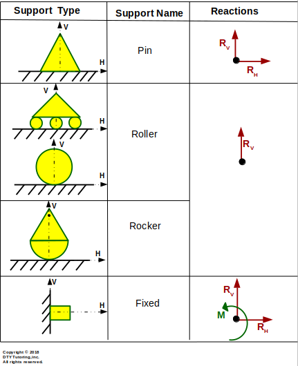 Figure 6:Reaction supports
- Types of beams
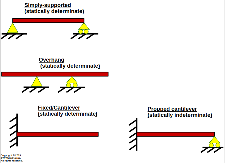 Figure 7:Types of beams
- Types of loads
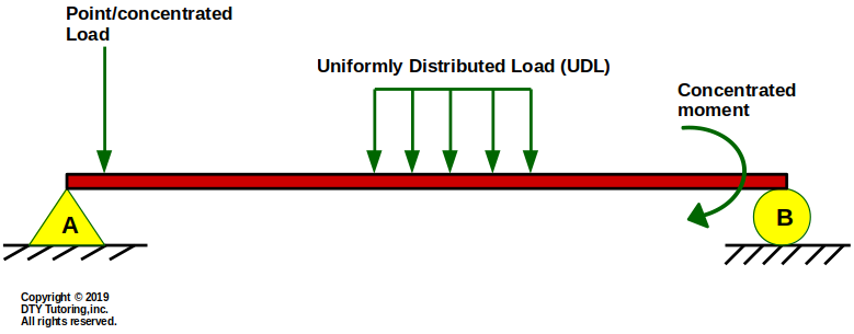 Figure 8:Types of loads
- Difference Between Tensile Compressive and Shear Forces
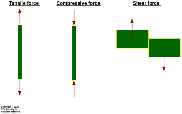 Figure 9: Difference Between Tensile, Compressive and Shear Forces
Reactions
- Finding reactions Example 1
This simply supported beam is supported by a pin at A, a roller at B, and has a point load at the midspan, find the reactions at A and B.
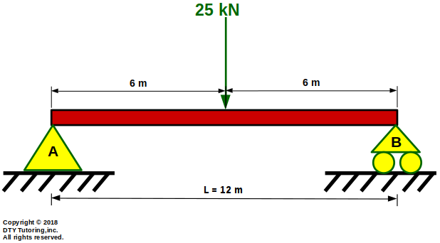 Figure 10: Simply supported beam with a point load at the midspan
- Finding reactions Example 2
This simply supported beam is supported by a pin at A , a roller at B, and has a uniformly distributed load acting throughout the entire span, find the reactions at A and B.
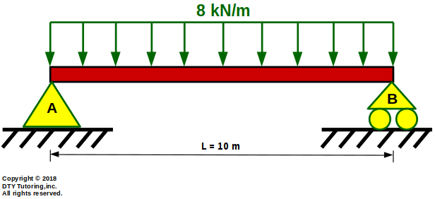 Figure 11: Simply supported beam with a uniform distributed load
- Finding reactions Example 3
The beam is supported by a rocker at A, roller at B and is subjected to a point load and concentrated moment. Calculate the reactions (in kN).
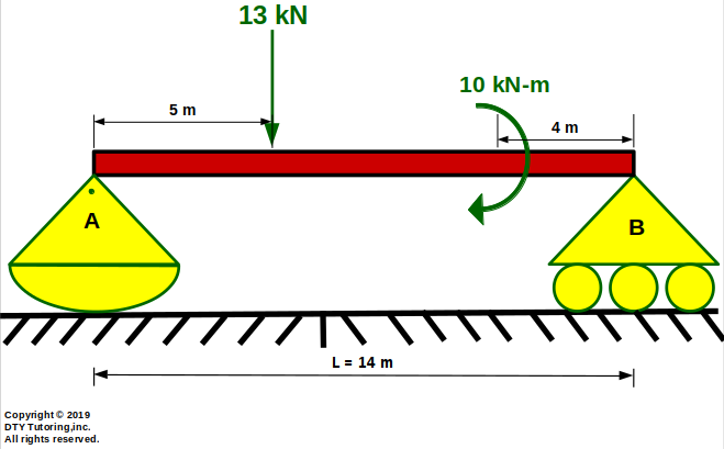 Figure 12:Rocker Roller beam with a point load and concentrated moment
- Finding reactions Example 4
The beam is supported by a fixed vertical roller at A, is pulled by a tension cable at B, and has no support at C. Find the reactions at A.
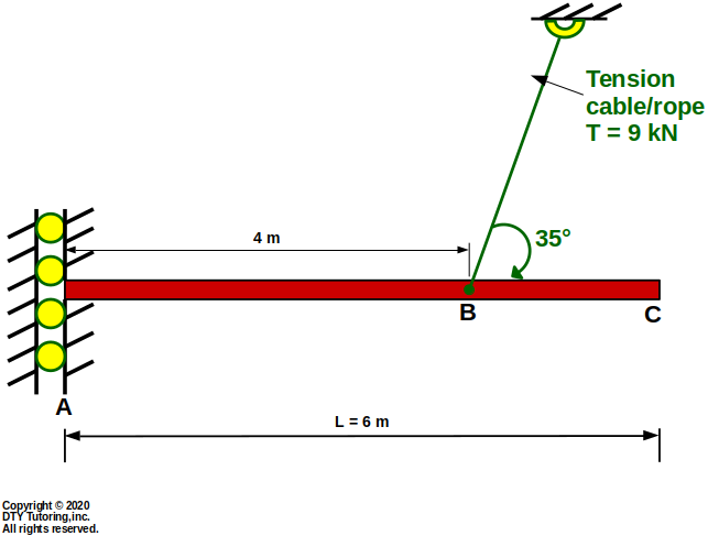 Figure 13:Fixed Vertical Roller Beam
- Finding reactions Example 5
Find the reactions for this beam with angled supports.
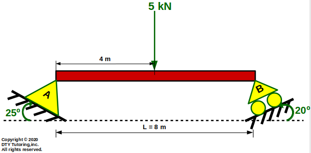 Figure 14: Simply Supported Beam with Angled Supports
- Finding reactions Example 6
The beam is supported by a fixed horizontal roller at A and is pulled by a tension cable at B. Find the reactions at A.
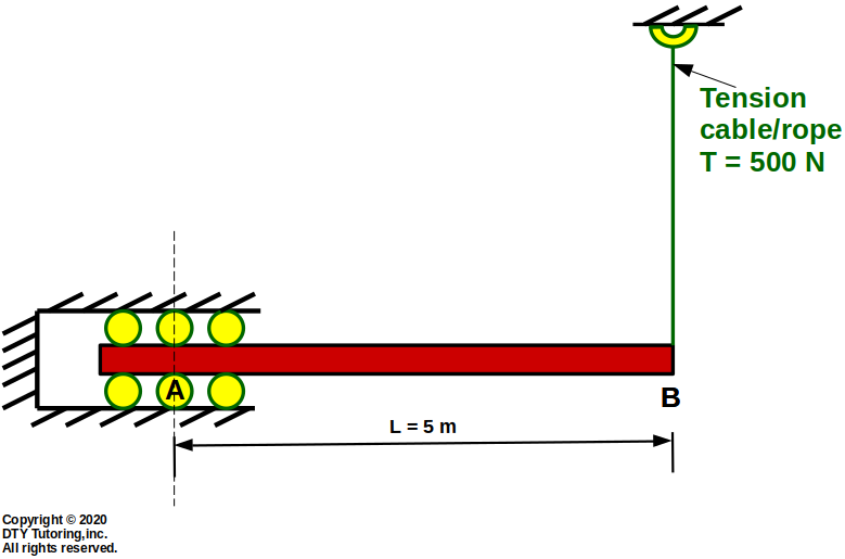 Figure 15: Fixed Horizontal Roller Beam with a Vertical Tension Cable
- Finding reactions Example 7
The beam is supported by a fixed horizontal roller at A, has an external load applied at B, and is pulled by a tension cable at C (TC = 700N). Find the force in member BD (FBD).
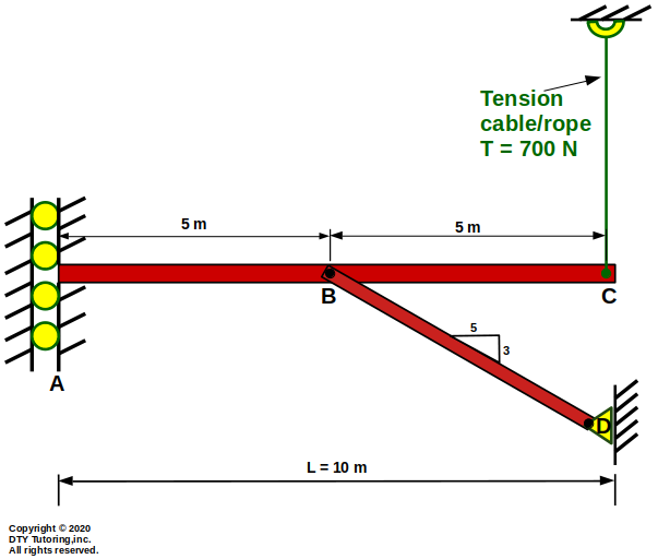 Figure 16: Fixed Vertical Roller Beam with a vertical Tension cable and An External Force
Trusses
Forces in a truss are transmitted axially through the joints, each member of the truss consists of a "2 force member". In order to find the internal force in a truss, 2 methods can be applied:
- Method of joints: ideal when used to find internal forces in all members of the truss,
- Method of sections: ideal when used to find internal forces in only some of the members of the truss (can only cut 3 members at once).
- Finding internal forces in trusses (using Method of Sections Example)
The truss shown below is supported by a pin at A and a roller at H. Compute the forces in member CE, BE and BD and indicate whether the members are in tension (T) or compression (C).
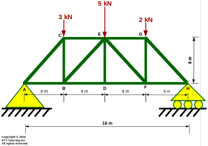 Figure 17: Method of Sections Example 1
- Finding internal forces in trusses (using Method of Joints Example)
Compute the forces in each member, indicate whether the members are in tension (T) or compression (C) and identify all zero force members.
Figure 18: Method of Joints Example 1
- Finding internal forces in trusses (using Method of Sections Example)
The horizontal bowstring truss shown below is supported by a pin at A and a roller at L. Compute the forces in member DF, EF and EG and indicate whether the members are in tension (T) or compression (C).
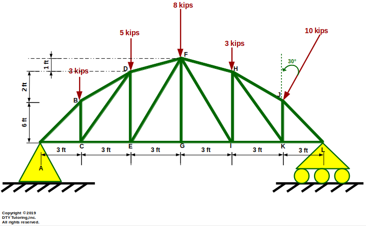 Figure 19: Bowstring truss
- Finding internal forces in trusses (using Method of joints Example)
The horizontal bowstring truss shown below is supported by a pin at A and a roller at L. Compute the forces in each member, indicate whether the members are in tension (T) or compression (C) and identify all zero force members.
Figure 20 : Bowstring truss
- Finding internal forces in trusses (using Method of Sections Example)
The horizontal fink truss shown below is supported by a pin at A and a roller at G. Compute the forces in member CD, BF and BD and indicate whether the members are in tension (T) or compression (C).
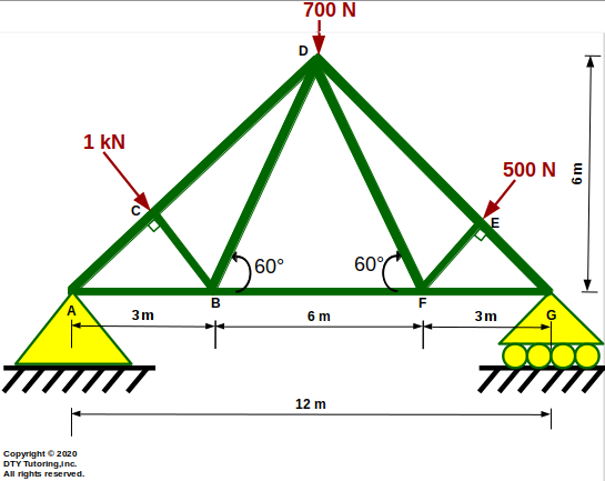 Figure 21: Fink truss
- Finding internal forces in trusses (using Method of joints Example)
The horizontal fink truss shown below is supported by a pin at A and a roller at G. Compute the forces in each member, indicate whether the members are in tension (T) or compression (C) and identify all zero force members.
Figure 22 : Fink truss
- Finding internal forces in trusses (using Method of Sections Example)
The horizontal double howe truss shown below is supported by a pin at A and a roller at L. Compute the forces in member GI, HF and FI and indicate whether the members are in tension (T) or compression (C).
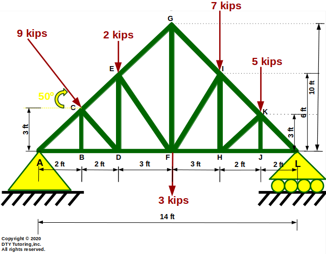 Figure 23 : Double Howe truss
- Finding internal forces in trusses (using Method of joints Example)
The horizontal double howe truss shown below is supported by a pin at A and a roller at L. Compute the forces in each member, indicate whether the members are in tension (T) or compression (C) and identify all zero force members.
Figure 24: Double Howe Truss
- Finding internal forces in trusses (using Method of Sections Example)
The horizontal truss shown below is supported by a pin at A and a roller at H. Compute the forces in member EG, EF and DF and indicate whether the members are in tension (T) or compression (C).
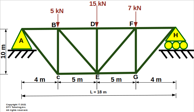 Figure 25 : Horizontal truss
- Finding internal forces in trusses (using Method of joints Example)
The horizontal truss shown below is supported by a pin at A and a roller at H. Compute the forces in each member, indicate whether the members are in tension (T) or compression (C) and identify all zero force members.
Figure 26 : Horizontal Truss
- Finding internal forces in trusses (using Method of Sections Example)
The horizontal pratt truss shown below is supported by a pin at A and a roller at M. Compute the forces in member HJ, GJ and GI and indicate whether the members are in tension (T) or compression (C).
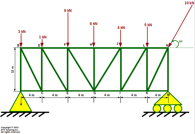 Figure 27 : Pratt Truss
- Finding internal forces in trusses (using Method of joints Example)
The horizontal pratt truss shown below is supported by a pin at A and a roller at M. Compute the forces in each member, indicate whether the members are in tension (T) or compression (C) and identify all zero force members.
Figure 28 : Pratt Truss
- Finding internal forces in trusses (using Method of Sections Example)
The horizontal K truss shown below is supported by a pin at A and a roller at O. Compute the forces in member EH, IK and IL and indicate whether the members are in tension (T) or compression (C).
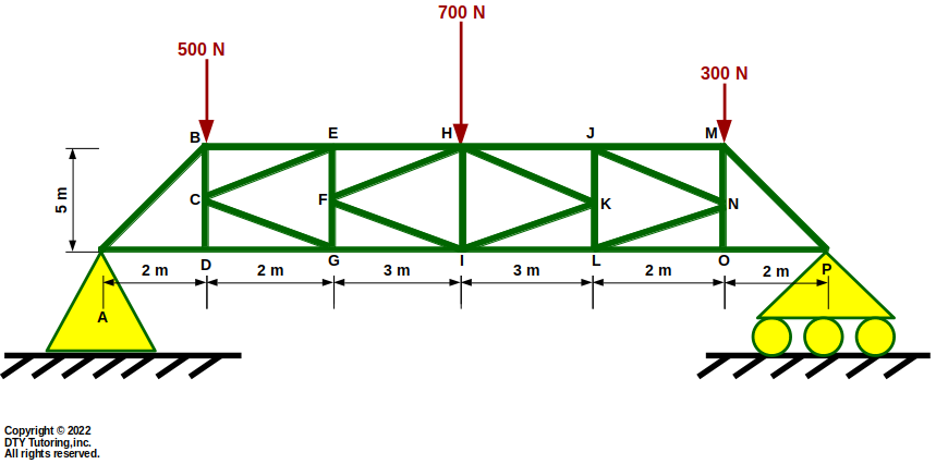 Figure 29: K Truss
- Finding internal forces in trusses (using Method of joints Example)
The horizontal K truss shown below is supported by a pin at A and a roller at O. Compute the forces in each member, indicate whether the members are in tension (T) or compression (C) and identify all zero force members.
Figure 30: K Truss
- Finding internal forces in trusses (using Method of Sections Example)
The vertical truss shown below is supported by a pin at A and a roller at B. Compute the forces in member EC, CF and DF and indicate whether the members are in tension (T) or compression (C).
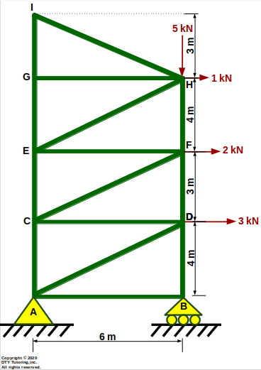 Figure 31: Vertical Truss
- Finding internal forces in trusses (using Method of joints Example)
The vertical truss shown below is supported by a pin at A and a roller at B. Compute the forces in each member, indicate whether the members are in tension (T) or compression (C) and identify all zero force members.
Figure 32: Vertical Truss
Frames and Machines
- Finding internal forces in frames and machines Example 1
The structure shown below has a roller support at A and is pinned at B and D, consisting of rigid frames and pulleys. Find the reactions at A, B and D for the frames and machines if m1 = 100 kg and m2 = 150 kg.
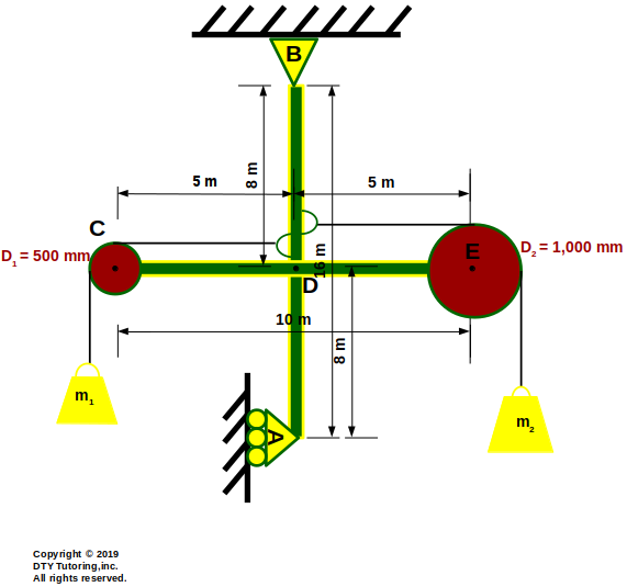 Figure 33: Frames and Machines Example 1
- Finding internal forces in frames and machines Example 2
![]() Figure 34:
Figure 34:
Shear and Moment diagrams
Steps to draw shear and moment diagrams
↪
Relationships between Loading, Shear and Moment diagram
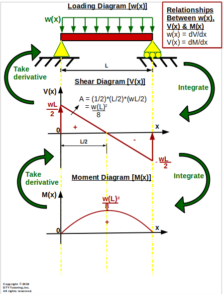 Figure 35 : Relationships between Loading, Shear and Moment diagram
Derivation of Shear (V(x)) and Moment (M(x)) Equations for a Simply Supported Beam With Uniform Distributed Loading (UDL)
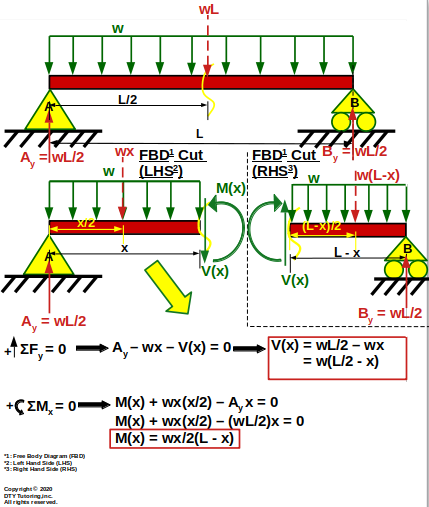 Figure 36: Derivation of Shear (V(x)) and Moment (M(x)) Equations for a Simply Supported Beam With Uniform Distributed Loading
Derivation of Shear (V(x)) and Moment (M(x)) Equations for a Simply Supported Beam With Triangular Distributed Loading
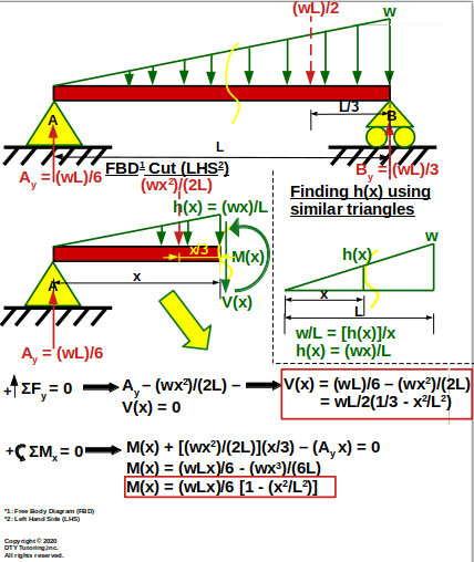 Figure 37: Derivation of Shear (V(x)) and Moment (M(x)) Equations for a Simply Supported Beam With Triangular Distributed Loading
Derivation of Shear (V(x)) and Moment (M(x)) Equations for a Fixed Beam With Uniform Distributed Loading (UDL)
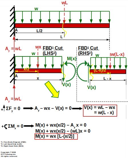 Figure 38 : Derivation of Shear (V(x)) and Moment (M(x)) Equations for a Fixed Beam With Uniform Distributed Loading (UDL)
Derivation of Shear (V(x)) and Moment (M(x)) Equations for a Fixed Beam With Triangular Distributed Loading
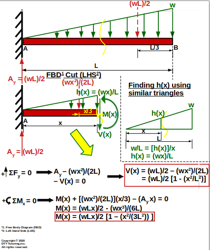 Figure 39: Derivation of Shear (V(x)) and Moment (M(x)) Equations for a Fixed Beam With Triangular Distributed Loading
- Drawing Shear (V) and Moment (M) diagrams Example 1
This simply supported beam is supported by a pin at A , a roller at B, and has a uniformly distributed load acting throughout the entire span, draw the shear and moment diagrams.
Figure 40 : Simply supported beam with a uniform distributed load
- Drawing Shear (V) and Moment (M) diagrams Example 2
This simply supported beam is supported by a pin at A , a roller at B, and has a triangular distributed load acting throughout the entire span, draw the shear and moment diagrams.
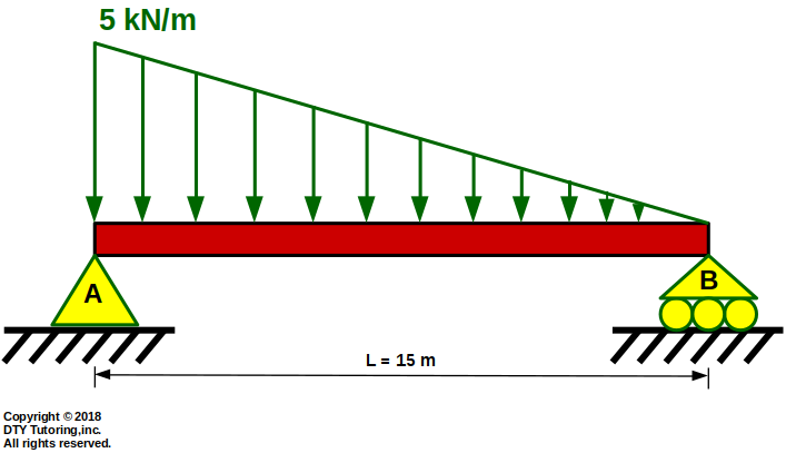 Figure 41 : Simply supported beam with triangular UDL
- Drawing Shear (V) and Moment (M) diagrams Example 3
This beam is fixed at A, free at C, has a uniform distributed load acting throughout half of the span, has a concentrated load and a concentrated moment, draw the shear and moment diagrams.
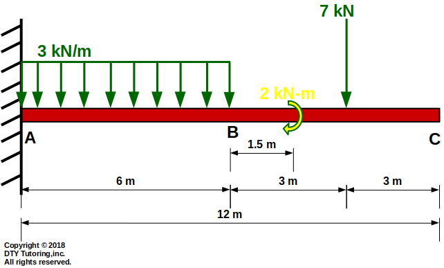 Figure 42 : Fixed beam with UDL, concentrated load and moment
- Drawing Shear (V) and Moment (M) diagrams Example 4
This beam is supported by a pin at A, and a roller at C. It has a uniform distributed load acting throughout half of the span from B to C, and has a concentrated moment at midspan from A to B, draw the shear and moment diagrams.
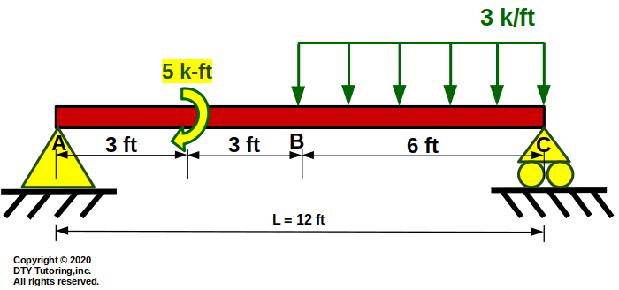 Figure 43: Simply Supported Beam with UDL and concentrated moment
- Drawing Shear (V) and Moment (M) diagrams Example 5
This beam is supported by a rocker at A, and a roller at C. A triangular distributed load is distributed from A to B, and a point load halfway from B to C, draw the shear and moment diagrams.
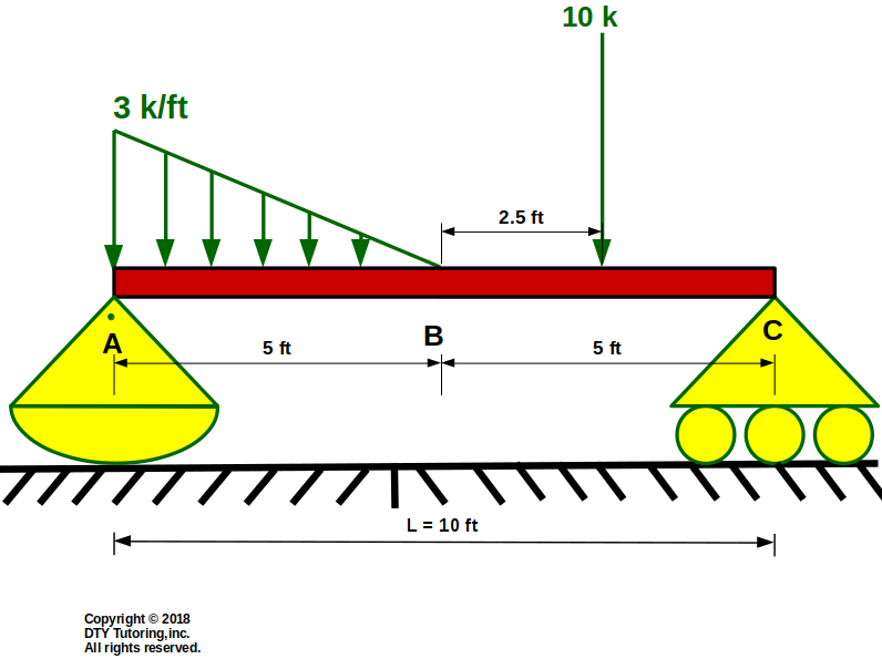 Figure 44: Rocker-roller support beam with a triangular distributed load and point load
- Drawing Shear (V) and Moment (M) diagrams Example 6
This beam is supported by a rocker at A, is fixed at C, and has a hinge at B. A concentrated moment is applied at C, and 2 point loads acting from A to B and B to C, draw the shear and moment diagrams.
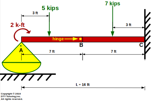 Figure 45: Fixed-rocker beam with hinge at midspan, 2 point loads and a concentrated moment
- Drawing Shear (V) and Moment (M) diagrams Example 7
Draw the shear and moment diagram for this overhang beam with a Uniformly Distributed Load (UDL) and a point load as shown below.
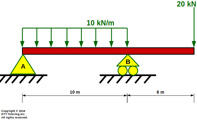 Figure 46:Overhang beam with a Uniformly Distributed Load (UDL) and a point load
- Drawing Shear (V) and Moment (M) diagrams Example 8
The beam is fixed at A, has a hinge at B and has a roller support at C. Draw the shear and moment diagram for this beam.
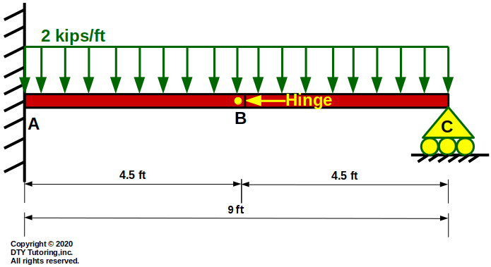 Figure 47:Fixed Roller Beam With Hinge
- Drawing Shear (V) and Moment (M) diagrams Example 9
Draw the shear and moment diagram for this overhang beam as shown below.
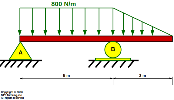 Figure 48:Overhang Beam With Distributed Load
- Drawing Shear (V) and Moment (M) diagrams Example 10
The beam is fixed at A, has hinges and continuous supports.Draw the shear and moment diagram for the beam.
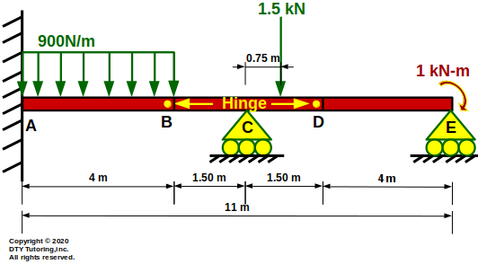 Figure 49: Fixed Continuous Beam With Hinges
- Drawing Shear (V) and Moment (M) diagrams Example 11
The beam has a Uniformly Distributed Loading (UDL) acting throughout the entire span and a concentrated moment at B. Draw the shear and moment diagram for the beam.
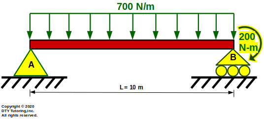 Figure 50: Simply Supported Beam With UDL and Concentrated Moment
- Drawing Shear (V) and Moment (M) diagrams Example 12
The beam has 3 point loads acting on it at equal distances. Draw the shear and moment diagram for the beam.
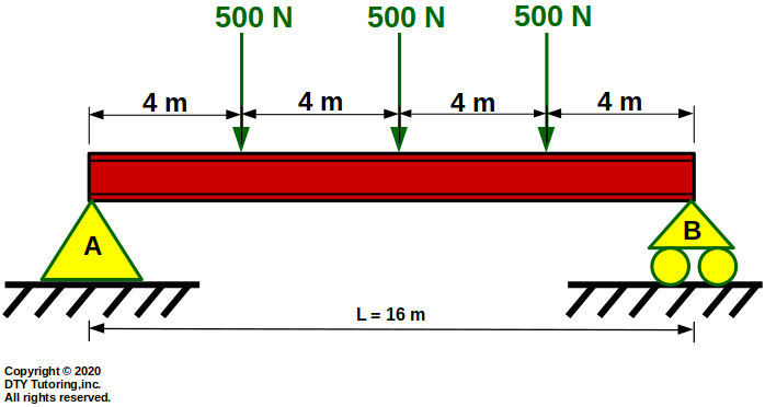 Figure 51: Simply Supported Beam With 3 Point Loads
- Drawing Shear (V) and Moment (M) diagrams Example 13
The overhang beam shown below has triangular distributed loading acting throughout its entire span and a concentrated moment. Draw the shear and moment diagram for the beam.
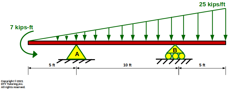 Figure 52: Overhang Beam with Triangular Distributed Loading and a Concentrated Moment
- Drawing Shear (V) and Moment (M) diagrams Example 14
The beam shown below is fixed at A, has a hinge at B and a roller support at C.There are 2 triangular distributed loadings acting throughout its entire span. Draw the shear and moment diagram for the beam.
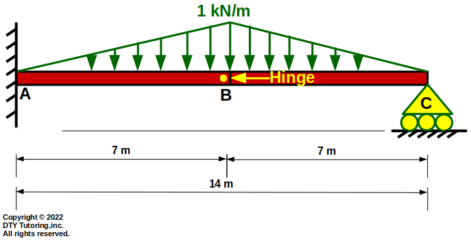 Figure 53: Fixed Roller Beam With a Hinge and 2 triangular Distributed Loadings
- Drawing Shear (V) and Moment (M) diagrams Example 15
The beam shown below is fixed at A, has a hinge at B, a pin at C, another hinge at D and a roller support at E.There are 2 triangular distributed loadings and 1 uniform distributed loading. Draw the shear and moment diagram for the beam.
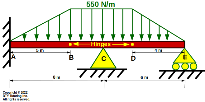 Figure 54: Fixed Pin Roller Beam With Distributed Loads and 2 Hinges
- Drawing Shear (V) and Moment (M) diagrams Example 16
The beam shown below is fixed at A, has a hinge at B, a roller support at C and D, another hinge at E and a concentrated moment at G.There are 2 triangular distributed loadings and 1 uniform distributed loading between the roller supports. Draw the shear and moment diagram for the beam.
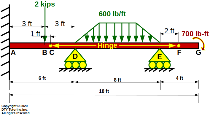 Figure 55: Fixed Continuous Beam With Distributed Loads and Hinges
Friction
- Solving a friction Example 1
![]() Figure 56:
Figure 56:
- Solving a friction Example 2
![]() Figure 57:
Figure 57:
Inertia
- Calculating inertia Example 1
Compute the moment of inertia about the centroid (Ix) for the hollow rectangular section given below.
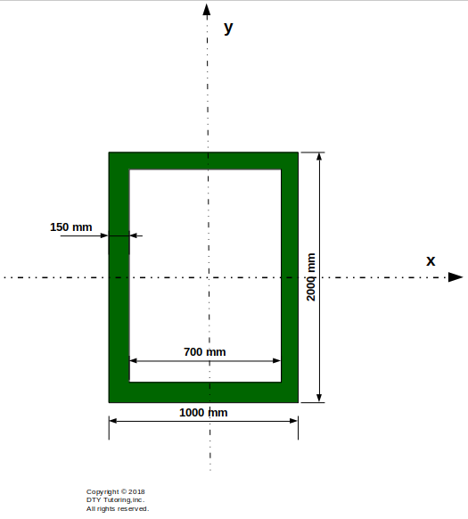 Figure 58: Finding the inertia for a rectangular hollow section
- Calculating inertia Example 2
Compute the moment of inertia about the centroid (Ix) for the T-shape section given below.
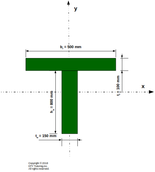 Figure 59: Finding the inertia for a T-shape beam
- Calculating inertia Example 3
Compute the moment of inertia about the centroid (Ix) for the channel section given below.
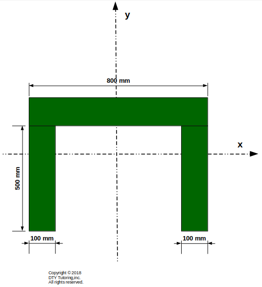 Figure 60: Finding the inertia for a rectangular hollow section