A beam is a horizontal structural member that is subjected to transverse loads.
Because members of a truss consist of '2 force members' where the loads are equal in magnitude but opposite in direction. The joint loads are transmitted axially so therefore there are no shear and moment in these types of structures; only axial loads exist.
A column is a vertical structural member that is subjected to axial loads.
The purpose of a footing is to transmit the load from the entire structure to the foundation.
A load path is the transmission of loads from one member (Ex: Beam) to the other (Ex: Girder), where the load is transferred downward, from the roof of the structure, all the way down to the foundation.
From Topics --> Steel Design page
Pros:
Can be used to design high-rise buildings (skyscrapers)
Has a good tensile and compressive strength (equally)
Is a ductile material, and is, therefore, strong enough to withstand external pressures (earthquake, wind, etc.)
Is a recyclable material and the recycled material can be used for the construction of a new structure (has good scrap value)
Is a lightweight material, therefore, it can span long distance
Does not require formwork, unlike concrete which makes it cheaper than reinforced concrete
Is easily erectable which speeds up the construction process and it is easy to assemble/disassemble the structure
Has less repair and maintenance costs compared to concrete
There is a variety of connections types (welds, bolts, rivets)
Cons:
Has less fire resistance compared to concrete, therefore, it needs fireproofing to resist fire damage; can melt at very high temperatures
Has buckling problems
Exact measurements have to be known before the transport and delivery of steel because the steel fabrication company does the manufacturing off-site (prefabrication)
Because you are designing based on the LOAD PATH which starts from the roof and ends at the foundation.
Mechanics is a branch of physics that deals with motion and the behavior of bodies under the effect of forces.
First law: "A body at rest will remain at rest, and a body in motion will remain in motion unless it is acted upon by an external force."(Equilibrium/Inertia)
Second law: "The force acting on an object is equal to the mass of that object times its acceleration." (Accelerated motion, F = ma)
Structural Analysis is the forecast of the performance of a structure under prescribed loading conditions. The results that are of interest are: the deflections, reactions and stresses.
From Topics --> Structural Analysis page
Inflection point (or point of contraflexure) is the point in the beam where the moment diagram changes sign (from + to - or vice versa) and is the point where the deflection curve changes the direction of curvature.
From Topics --> Structural Analysis page
Engineering Statics is one of the branches of rigid-body mechanics that focuses on the study of bodies in equilibrium/at rest (acceleration = zero) or with a constant velocity.
From Topics --> Engineering Statics page
Solid mechanics/mechanics of materials/strength of mechanics/mechanics of deformable mechanics is one of the branches of deformable-body mechanics that focuses on the study of solid objects that can change shape or size as a result of loading or thermal effects.
From Topics --> Mechanics of Materials page
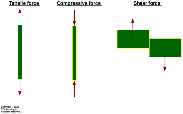
Difference Between Tensile, Compressive and Shear Forces
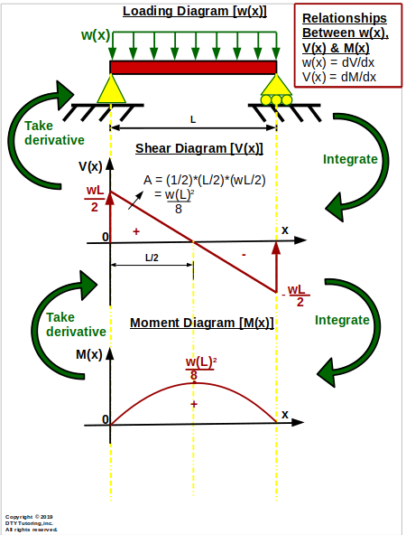
As you go from Loading diagram [w(x)] --> Shear diagram [V(x)] --> Moment diagram [M(x)], you have to integrate. But if you follow the opposite route from Moment diagram[M(x)] --> Shear diagram [V(x)] --> Load diagram [w(x)], you have to take the derivative. In other words, in terms of derivatives, you have the following relationships:
V(x) = dM/dx,
w(x) = dV/dx
Refer to image shown below.
Relationships between Loading, Shear and Moment diagram
Concrete is a mixture of fine and coarse aggregates that are held together by a cement paste (cement mixed with water) that hardens over time. Concrete = cement + water + sand + aggregate
Reinforced concrete is a composite material that combines the usage of both concrete and steel where the steel reinforcement is used to counteract the lack of tensile strength in concrete.
From Topics --> Reinforced concrete page
Pros:
Has good tensile strength compared to plain concrete
Is shapeless like water, it can be made into any kind of shape
Strength increases with age
Is fire resistant
Is a better material for a strong foundation because of its heaviness in weight, which is the reason why most building have a reinforced concrete foundation
Needs less skilled labor compared to steel
Cons:
Is more expensive than structural steel
Is a heavy material, therefore, it cannot span long distance like steel
Takes more time in construction compared to steel
Is not recyclable for the construction of a new structure (has nil scrap value)
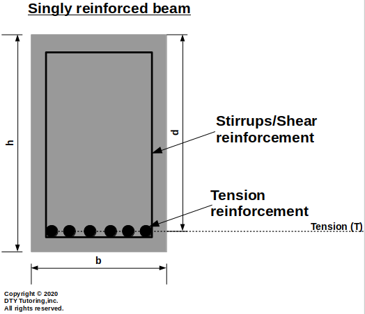
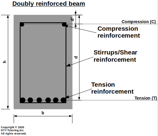
Tension reinforced section is when you have steel reinforcement (rebar) on the tension controlled region where the rebar is used to counteract the lack of tensile strength in concrete. When reinforcement is only present in the tension zone, you have a singly reinforced beam. Nevertheless, sometimes, rebar on the tension side only is not enough to resist the ultimate moment capacity of the beam, therefore, reinforcement in the compression region is needed. When reinforcement is present in both zones (tension and compression), you have a doubly reinforced beam.
Figure :Singly and doubly reinforced beam explanation From Topics --> Reinforced concrete page
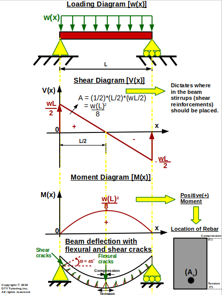
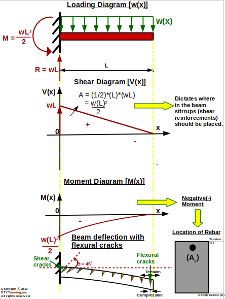
Yes the shear and moment diagram affects the arrangements of reinforcement bars in a beam. For example, arrangements of stirrups (also known as shear reinforcement) are governed by the shear diagram in a beam. Similarly, arrangement of rebars (also known as longitudinal reinforcement bar) are governed by the moment diagram. For example, in a cantilever beam subjected to Uniformly Distributed Loads (UDL) acting downward throughout the entire span of the beam, the flexural cracks will occur at the very top portion of the beam which means that tension is occurring at that point and compression is in the bottom; the moment diagram will be negative which suggests that rebar should be placed in the top portion of the beam. Refer to images shown below.
Figure 2: Relationship between Shear (V) and Moment (M) diagrams and steel reinforcements in a simply supported and cantilever beam From Topics --> Reinforced concrete page